Specifications are subject to change without notice
Drives
LOCKABLE DISCONNECT SWITCH (PG 169)
The lockable disconnect switch is designed to disconnect the main power
source, single or three phase.
CONTACTOR (PG 170)
The option of using a contactor ensures that the drive will not be damaged
due to any rapid fluctuations in power levels such as in a rainstorm or
thunderstorm where power may be cycling rapidly (check on the proper
electrical code for contactor and fuse configuration). In some types of
drives that have a standard DC Bus configuration the rapid cycling of line
side power may cause severe damage possibly requiring a new drive. This
is only a suggestion to be used in cases where heavy rainstorms occur and
the specific drive system is critical.
HIGH-SPEED FUSES (PG 158)
Most drives require high-speed fuses (also known as semiconductor rated
fuses). Because of their energy limiting characteristics, they are able to
protect semiconductor devices such as variable frequency drives from
excess energy let-through under fault current conditions.
The use of time delay fuses is not recommended as they are meant
for loads such as motors or heaters not electronic devices such as fax
machines, computers, and variable frequency drives.
LINE REACTOR (PG 154)
The line reactor is basically protecting the full wave rectifier on the front end
of the drive and the DC Bus (all those capacitors in the drive). It attenuates
most voltage anomalies and must be used were the voltage is 575 volts,
close to a power factor correction bank or where THD (Total Harmonic
Distortion) is high. The line reactor will attenuate most of these and is
always a good idea to use regardless since drives tend to be voltage
sensitive devices. N.B. The line reactor must be sized for the nominal load
that the drive is working at. If the line reactor is sized for the full load rating
and the drive only outputs half of its capability then the line reactor will not
provide adequate protection.
MOV SURGE PROTECTOR (PG 157)
The MOV Surge Protector will ensure that the full wave bridge rectifier on
the input side of the VFD will be protected from any dangerous voltage
transients and will reduce the effect of lightning. The use of an MOV is
recommended. This device is placed at the line reactor and is wired in
parallel with the incoming power line.
LOAD REACTOR/FILTER (PG 156)
)F THE MOTOR LEADS ARE WITHIN FEET IN LENGTH THEN NO ,OAD &ILTER IS
required as the motor windings will not experience any adverse effects
from Reflective Wave Phenomena. This applies to a Carrier Frequency
of 2.5KHZ; if higher, then leads must be shorter.
)F THE LEADS ARE OVER
FEET IN LENGTH THEN A ,OAD 2EACTOR &ILTER IS
required.
CONTROL WIRING (PG 157)
Control wiring to the drive from the station should be stranded, shielded and
18 to 24AWG in size. It should be wired directly to the input terminals of the
drive since dry contact signals are used for the discrete stop/start, forward/
reverse etc. The majority of control boards on most drives are totally iso-
lated from the drive itself and must not see any voltage via the control wire
to the drive’s control from either a radiated, conducted or
emitted source.
153
AC ADJUSTABLE SPEED DRIVES
GENERAL INFORMATION
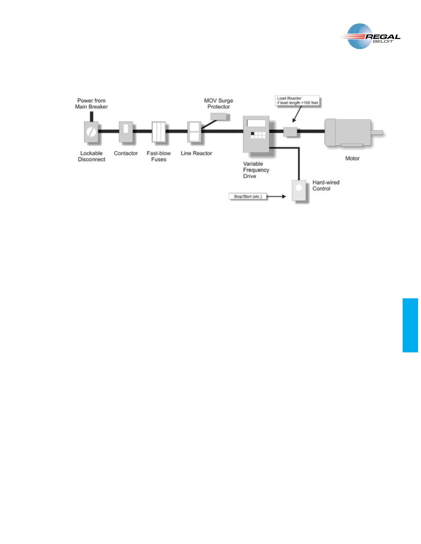
VARIABLE FREQUENCY DRIVE SET-UP
Figure 1: Layout of a Nema 1 style drive. Notice that line side
power, control wires, and motor leads each have their own conduit.
It is extremely important not to cross the motor lead wires with any
other wire. If an enclosure is used, motor lead wires must be kept
away from all other control and power wiring.
Installation of the VFD should entail some basic components (Figure 1).
The following is a brief description of these components.
N.B. As with all
electrical equipment installation must be done by certified or licensed
personnel. Always check with provincial and federal standards and
codes for your area.


