Specifications are subject to change without notice
Drives
Catalogue
Watts
Dimensions (Inches)
HP
Number
Amps
Loss
Height x Width x Depth
Weight
0.5
KDRA54L
2.4
7
4.00 x 4.18 x 3.75
4
0.75
KDRA53L
3.5
12
4.00 x 4.18 x 3.75
4
1
KDRA25L
4.6
11
4.00 x 4.18 x 3.75
4
1.5
KDRA26L
6.6
18
4.00 x 4.18 x 3.75
4
2
KDRA27L
7.5
21
4.00 x 4.18 x 3.75
4
3
KDRA28L
10.6
29
4.00 x 4.18 x 3.75
4
5
KDRB22L
16.7
38
5.00 x 6.00 x 4.00
8
7.5
KDRB23L
24.2
48
5.00 x 6.00 x 4.00
8
10
KDRD25L
30.8
64
5.75 x 7.20 x 4.25
12
15
KDRD24L
46.2
85
5.75 x 7.20 x 4.25
12
20
KDRD26L
59.4
94
5.75 x 7.20 x 4.25
12
25
KDRC22L
74.8
114
5.75 x 7.20 x 5.00
15
30
KDRF24L
88
135
7.00 x 9.00 x 6.00
30
40
KDRF25L
114
149
7.00 x 9.00 x 6.00
30
50
KDRF26L
143
154
7.00 x 9.00 x 6.00
30
60
KDRH22L
169
209
9.00 x 11.00 x 7.00
45
75
KDRI23L
211
294
9.00 x 11.00 x 7.00
50
100
KDRI24L
273
276
9.00 x 11.00 x 7.00
50
125
KDRG22L
343
370
9.00 x 11.00 x 8.00
65
150
KDRJ23L
396
401
9.00 x 11.00 x 9.00
70
200
KDRJ24L
528
442
9.00 x 11.00 x 9.00
70
154
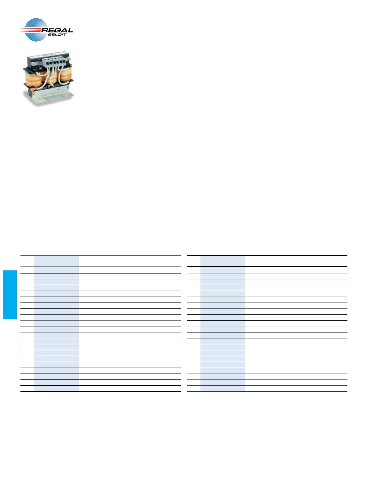
,%%3/. THREE PHASE !# REACTORS ARE INTENDED
for use as input (or output) filters for variable
frequency drives. Drive performance is improved
by protecting the input rectifier from failure or
damage and acting as a buffer between the line
and the solid state power circuit.
Transient voltages on the AC power line can
cause inrush currents to an AC drive. These
transient voltage conditions are often caused by
utility capacitor switching. The addition of a line
reactor will limit the magnitude of inrush current
preventing tips and component failures.
ÓänÓ{ä6ÊUÊ "7Ê<®Ê * Ê
Low “Z” units can be used in any application where traditionally either a
1.5% or 3% impedance reactor would be applied.
Features
s ,IFETIME WARRANTY
s 5NIVERSAL FOOTPRINT
s !LL COPPER WINDINGS
s #3! CERTIFIED
s 5, 5,# RECOGNIZED
The new KDR Optimized Drive Reactors have been designed to provide the
rugged reliability customers have come to expect. These reactors are now
available for both the input and the output of PWM drives.
4HE +$2 REACTORS FOR THE INPUT ARE AVAILABLE IN TWO RATINGS VERSIONS ,OW h:v
LOW IMPEDANCE AND (IGH h:v HIGH IMPEDANCE 4HE ,OW h:v UNITS CAN BE USED
in any application where traditionally either a 1.5% or 3% impedance reactor
would be applied. The High “Z” units can be used in any application where
traditionally a 5% impedance reactor would be applied.
The output reactors (see page 119) have been selected based on the unit’s
ability to withstand the rigors of variable system characteristics. With TCI’s same
outstanding warranty and performance guarantee, the KDR Optimized Drive
Reactors offer a superior design and performance solution.
"*/ < Ê , 6 Ê, /",-ÊUÊ ,
AC ADJUSTABLE SPEED DRIVES
INPUT LINE REACTORS
Catalogue
Watts
Dimensions (Inches)
HP
Number
Amps
Loss
Height x Width x Depth
Weight
0.5
KDRA54H
2.4
14
4.00 x 4.18 x 3.75
4
0.75
KDRA53H
3.5
16.8
4.00 x 4.18 x 3.75
4
1
KDRA25H
4.6
23.6
4.00 x 4.18 x 3.75
4
1.5
KDRA27H
6.6
30.6
4.00 x 4.18 x 3.75
4
2
KDRA26H
7.5
30.5
4.00 x 4.18 x 3.75
4
3
KDRA28H
10.6
43.1
4.00 x 4.18 x 3.75
4
5
KDRB25H
16.7
53.1
5.00 x 6.00 x 4.00
8
7.5
KDRB26H
24.2
66.5
5.00 x 6.00 x 4.00
8
10
KDRD21H
30.8
91.8
5.75 x 7.20 x 4.25
12
15
KDRD22H
46.2
107.8
5.75 x 7.20 x 4.25
12
20
KDRC22H
59.4
113.1
5.75 x 7.20 x 5.00
15
25
KDRF28H
74.8
151
7.00 x 9.00 x 6.00
30
30
KDRF25H
88
179.2
7.00 x 9.00 x 6.00
30
40
KDRF26H
114
192.8
7.00 x 9.00 x 6.00
30
50
KDRH24H
143
201
9.00 x 11.00 x 7.00
38
60
KDRH23H
169
220
9.00 x 11.00 x 7.00
45
75
KDRI22H
211
311.5
9.00 x 11.00 x 7.00
50
100
KDRI21H
273
296.4
9.00 x 11.00 x 7.00
50
125
KDRG25H
343
346.5
9.00 x 11.00 x 8.00
65
150
KDRJ22H
396
465.3
9.00 x 11.00 x 9.00
70
200
KDRJ21H
528
516.2
9.00 x 11.00 x 9.00
70
ÓänÓ{ä6ÊUÊ
Ê<®Ê * Ê
High “Z” units can be used in any application where traditionally a 5%
impedance reactor would be applied.


