165
Specifications are subject to change without notice
Drives
#ATALOGUE
,INE
!#
&EEDBACK
-AX 2EF
0OWER 3UPPLY
3PEED
&EEDBACK
!PP
.UMBER
6OLTAGE
,INE 0OWER
3OURCES
6OLTAGE
6OLTAGE FOR & " $EVICES 2EGULATION &REQ 2ANGE 7GT LBS
DLC600
OR
6
WATTS
s (ALL %FFECT
6$# 6$# OR
6$#
(:
(:
s %LECTROMAGNETIC 0ICK UP
s OR
6$# .0. TYPE ENCODER
or proximity switch
s %NCODER
Catalogue
Number
Size
HP Range
Input (AC)
Output (DC)
MD10P
1/8 DIN
.15A-1/2
120V
0-90V
1/8-1
240V
0-180V
MD3P
1/4 DIN
1/4-1
120V
0-90V
1/4-2
240V
0-180V
#ATALOGUE
,INE
&EEDBACK
&EEDBACK
0OWER 3UPPLY
!PP
Number
Voltage
Sources
Freq. Range
Voltage for F/B Devices
Wgt. (lbs.)
VT8-D230AC
6!#
s (ALL %FFECT
(:
6$# OR
s %LECTROMAGNETIC
6$#
Pick-up
DC ADJUSTABLE SPEED DRIVES
SIGNAL PROCESSORS
CLOSED LOOP CONTROLS - DLC Series
4HE $,# PRECISELY CONTROLS YOUR
closed loop application speed. The
$,# S DUAL VOLTAGE CAPABILITY LINE
ALLOWS IT TO REPLACE BOTH -INARIK S $,#
6!# $,#
6!# AND
$,#
6!# !N ENCODER OR
proximity switch, Hall effect sensor, or
electromagnetic pickup can provide the
necessary feedback. Any engineering
units, from revolutions per minute to
widgets per day, can be used to display
and program the speed. The large
DIGIT ,%$ DISPLAY ALLOWS YOU TO EASILY SEE EXACTLY WHAT SPEED YOU ARE
RUNNING 7HEN IT COMES TO LOW COST CLOSED LOOP CONTROL THE $,# IS YOUR
solution.
Features:
s
Excellent Speed Regulation:
0.05% speed regulation of set speed
provides tight control throughout a 200:1 speed range.
s
Pushbutton Programming:
Three front panel pushbuttons provide quick
and easy programming.
s
4-Digit LED Display:
0.5 inch (13 mm) wide digits for good visibility.
s
Programmable Decimal Point:
Makes specific application readouts
easy.
s
Inhibit Terminal:
A low voltage, dry contact closure on the inhibit terminal
will reduce the output to zero.
s
Selectable Feedback Devices:
Controls accept magnetic pick-up, Hall
effect, inductive proximity sensor or encoder input.
s
+5 VDC or +12 VOC (10 mA) Power Supply:
Provides power to
feedback devices.
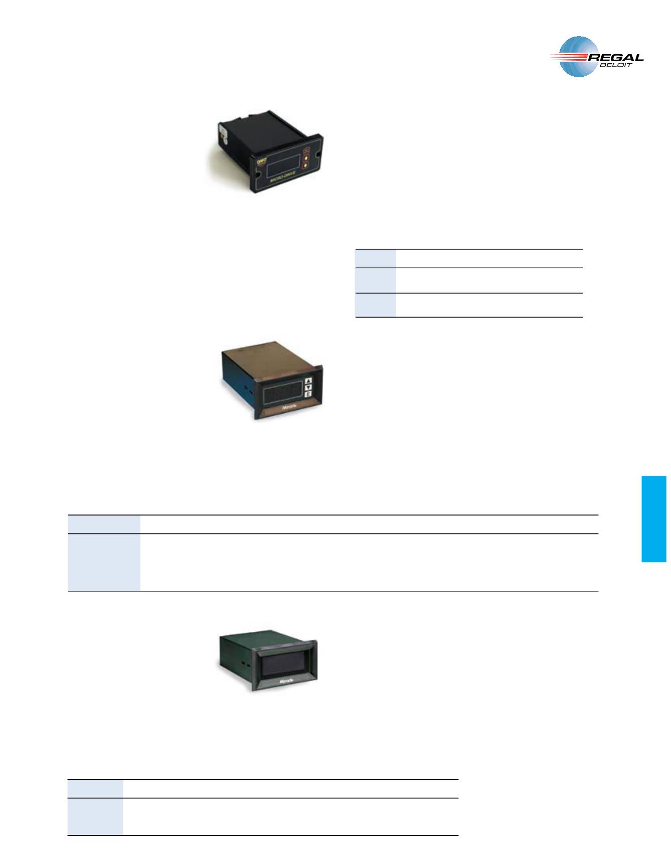
CLOSED LOOP CONTROLS - MD Series
A compact, programmable DC speed
control with digital closed loop feedback
AND ,%$ DISPLAY FOR $# MOTORS RATED
to 2 HP. An on-board micro-processor
with non-volatile memory, coupled with
sophisticated internal software, makes
the Micro-Drive the ultimate value in
accuracy and control.
Friendly front-panel field programming
permits customizing the MD for
specific applications. The MD can be set to display the target speed directly in
RPM, FPM, GPM, process time, or any other engineering unit. Programmable
parameters include maximum and minimum set speed, decimal points, operating
mode (master or follower), and the constant which takes into account motor gear
ratios.
Features:
s 5SER FRIENDLY
programming from the front panel with parameter lockout
capability
s 0ROGRAMMING BUTTONS HAVE ADJUSTABLE RATE AND MODE
; linear or non-linear
s $ISPLAY IS PROGRAMMABLE
for any engineering unit of measure
s $ISPLAY OPTIONS INCLUDE
zero-blanking, decimal point positions, and intensity
s #USTOM FRONT PANEL
artwork available
s %ASY PANEL MOUNTING
with 2 or 4 bolts (supplied)
s .%-! 8 2ATING
(faceplate with supplied gasket)
s 5NIVERSAL POWER SUPPLY
supports any AC voltage input from 85 - 265 VAC
s 0ROGRAMMABLE USER OUTPUT
supporting up to 230 VAC @ 5A
s -ULTIPLE OPERATIONAL MODES
Rate, Time, Follower Options
/ Ê, / Ê /",ÊÊ6/nÊ- , -ÊUÊ 1 Ê6" /
The VT8 Series is a great choice in a
digital tachometer.
The VT8 Series provides a simple and
accurate readout for any object that has
an optical encoder, magnetic pickup,
or anything else that can generate a
frequency related to what you wish to
measure.
There are four modes to choose from: tachometer mode for speed in
any engineering unit, time-in-process for indicating the duration of an
application, the inverse of speed (such as minutes per revolution), and
basic totalizer for counting the frequency of the speed sensor.
Features:
s
Four Operating Modes:
1) speed of application or multiple,
2) time-in-process indicating duration of application,
3) the inverse speed (i.e., minutes per revolution)
4) number of counts received from feedback device.
s 3ELECTABLE &EEDBACK $EVICES
Displays accept magnetic pickup, Hall
effect, inductive proximity sensor or encoder input.
s
6$# #M! OR
6$# M!
Provided to power feedback
device.
s 7IDE &REQUENCY 2ANGE
Accepts 0 - 20,000 Hz from feedback device.
s %ASY TO 2EAD $ISPLAY
DIGIT ,%$ DISPLAY IS v
MM


