195
Electrical
Dual ON/ OFF Delays Fan Controls
Part #
Features & Applications
Specifications
Cross Reference
24-ICM251
• Drives fan directly.
• High power, relay output.
• Dual function fan delay timer.
• Controls the circulating fan in heat pump, A/C
and forced air systems.
• OFF delay controls fan relay to purge ducts of
residual air at the end of the heating/ cooling
cycle.
• ON delay allows air to reach the proper comfort
level prior to energizing the fan.
• Control: 18-30 VAC.
• Output:
N.O. 20 amps @ 240 VAC.
N.C. 10 amps @ 240 VAC.
• Time delays: fixed or adj.
ON: 1 to 180 sec.
OFF: 12 to 390 sec.
Mars
• 32377
• 32378
• 32379
24-ICM254
• Dual function fan delay timer.
• Controls the circulating fan in heat pump, A/C
and forced air systems.
• OFF delay controls fan relay to purge ducts of
residual air at the end of the heating/ cooling
cycle.
• ON delay allows air to reach the proper comfort
level prior to energizing the fan.
• Control: 18-30 VAC.
• 1 amp maximum.
• 40 mA minimum.
• 10 amp inrush.
• Time delays: fixed or adj.
ON: 1 to 180 sec.
OFF: 12 to 390 sec.
Honeywell
• S876A1016
Watsco
• PSTD-000-005W
• PSTD-000-060W
24-ICM255
• Low cost open board design.
• High power, relay output.
• Dual function fan delay timer.
• Controls the circulating fan in heat pump, A/C
and forced air systems.
• OFF delay purges ducts of residual air.
• ON delay allows air to reach the proper comfort
level prior to energizing the fan.
• Control: 18-30 VAC.
• Output:
N.O. 20 amps @ 240 VAC.
N.C. 20 amps @ 240 VAC.
• Time delays: fixed.
ON: 1 sec.
OFF: 60 sec.
Bard
• 8201-056
Mars
• 32393
Snyder-General
• 1395336
Watsco
• 5893
Rheem
• 42-22515-01
• 42-22515-02
• 42-22515-03
Fan Blower Control
Fan Blower Control
Applications
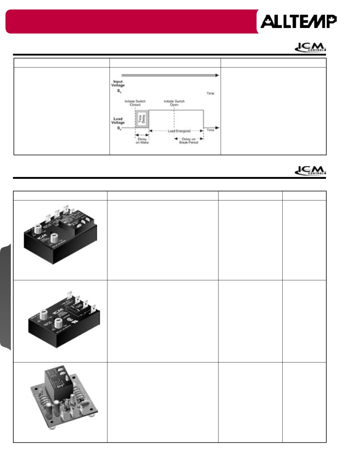
Timing Diagram
Mode Of Operation
• "On delay on break" and
• "Off delay on break"
• Controls the circulating fan in heat pump,
air conditioning and forced air systems.
On delay on make lets air reach proper
level prior to turning on the fan. Off
delay timing function continues to run
the fan at the end of the heating/ cooling
cycle, thereby purging ducts of residual
air and increasing system efficiency.
• Power must be applied before and during the
time delay period. When the initiate contact
closes, the delay on make period begins.
The load then energizes and remains
energized as long as the initiate contact is
closed. The delay on break period begins
when the initiate contact opens. At the end
of the time delay, the load is turned off. If the
initiate contact recloses during the time delay,
the load is reset to zero. Removal of input
power during the delay turns off the load and
resets the time delay to zero.
Solid State Components


